
Counterbalance Mechanism<em>.</em>
Counterbalance Mechanism
KR-CBM (CounterBalance Mechanism)
Product overview
- A counterbalance mechanism (CBM) or passive gravity compensator can minimize the torque required to maintain the posture of a robot by appropriately compensating for the gravitational torque generated by both the weight of the robot and payload.
- When applied to collaborative robots, the CBM enables a 1.5 to 2 times increase in payload while using the same motors.
- 1 DOF counterbalancing is mainly performed by installing the CBM only at joint 2, where the largest gravitational torque occurs, but the maximum gravity compensation effect can be obtained by 2 DOF counterbalancing with CBMs installed at both joints 2 and 3.
Benefits of using CBMs
- It is possible to implement a 25 kg (30 kg) payload collaborative robot with the medium-sized motors used for a 15 kg (20 kg) payload collaborative robot.
- For the same payload, a low-capacity motor can be used, resulting in energy savings (30 to 35%) and relatively safer in case of malfunction. Hence, it is suitable for mobile robot arms. Hence, it is suitable for mobile robot arms.
- Compatible with the existing collaborative robot controller with minor mechanical modifications.
Why is CBM essential for collaborative robots?
- Unlike industrial robots, which can increase payload simply by using higher-power motors, collaborative robots operating in the same space as humans cannot use high-capacity motors that require high voltage (e.g., 96 V, 200 V) for safety reasons. According to IEC62386, machines working with humans are limited to DC 60 V or less for safety. Therefore, CBMs are necessary to increase payload or reach without compromising safety or using high-voltage motors.
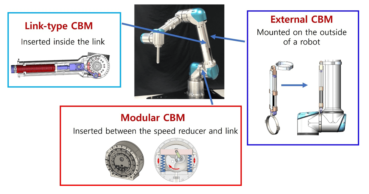
Types
- Link-type CBM (LCBM): Delivered in a long rod form using a coil spring. It is installed in the empty space of link 2 and must be dimensioned and mounted according to the robot’s geometry. Connected in parallel with the robot, it has no impact on robot stiffness.
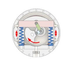
- Modular CBM (MCBM): Provided in the form of a module (similar to a harmonic drive). Inserted between link 2 and joint 2 requiring minimal mechanical modification. Connected in series, it slightly reduces the robot stiffness.
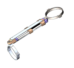
- External CBM (ECBM): Mounted externally via clamping, requiring no modifications to the robot’s mechanical structure. Connected in parallel, it has no impact on robot stiffness.
Product specifications
| Model | LCBM | MCBM | ECBM | |||
|---|---|---|---|---|---|---|
| Shape | 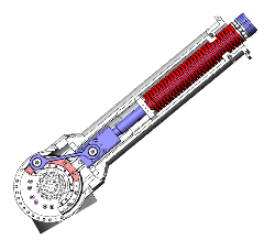 |
 |
 |
|||
| Spring type | Coil spring | Gas spring | Gas spring | |||
| Mounting location | Inside link 2 | Between joint 2 and link 2 | Outside link2 | |||
| Mounting feature | Link 2 needs to be slightly redesigned. | The mounting interface at joint 2 needs to be modified. | Mounted directly onto the existing robot | |||
| Connection | Parallel connection | Series connection | Series connection | |||
| Robot stiffness | No change | 10% decrease at joint 2 | No change | |||
| Compensation torque | 100 – 650 Nm (1 spring), 1300 Nm (2 springs) | 100-300 Nm | 100-300 Nm | |||
| CBM hysteresis | Almost none | Relatively large hysteresis | Relatively large hysteresis | |||
| Control performance | Applying CBMs has no impact on the control performance | |||||